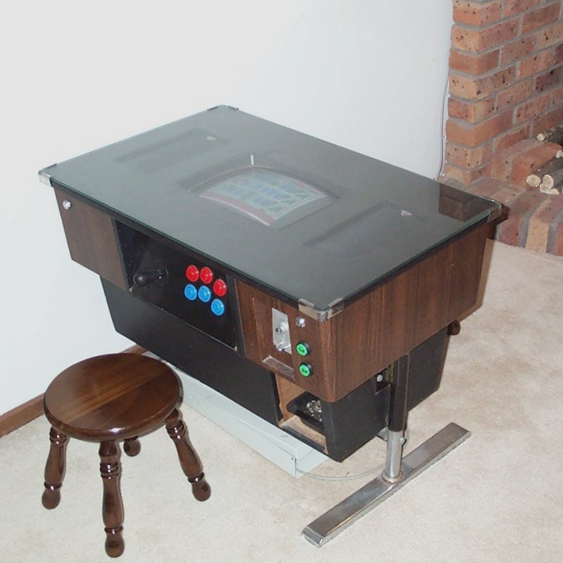
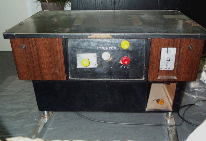
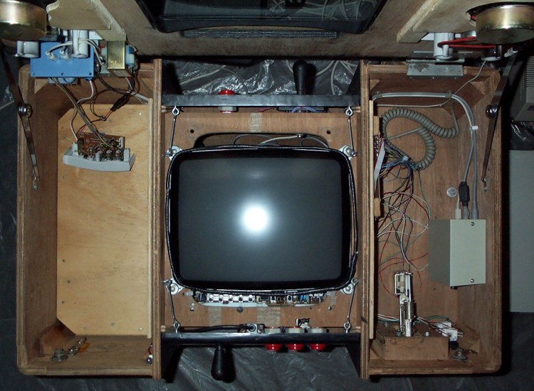
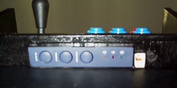
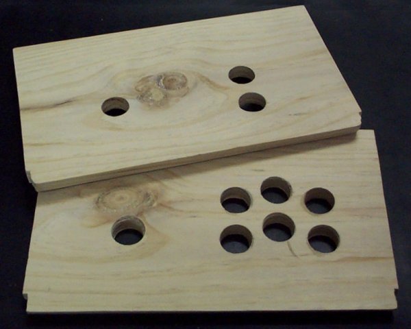
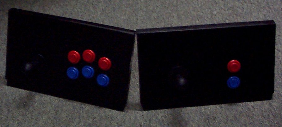
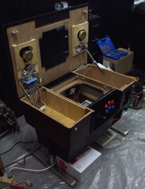
The original controls were in bad shape, and there was only 1 button per player, so games like elevator action were unplayable. I decided on 6 buttons for player 1 and 2 buttons for player 2. The 1&2p start buttons have LEDs to indicate when there are enough credits to use them.
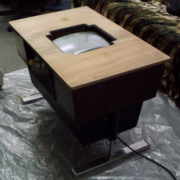
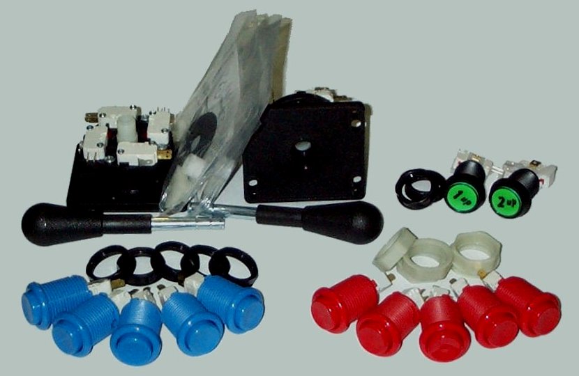
I ordered the parts online from Happ Controls in the US. It was a simple matter of cutting & drilling a couple of bits of wood, painting them, then mounting the controls.
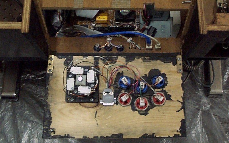
Player 1's controls - PC game port joystick interface
I collected the background info on the PC joystick from several sites. I've put them all here as none of the individual sites covered everything you need to build a set of arcade controls. The usual disclaimer applies to all information here... if you damage anything, then it's your fault, not mine. :)
Building the circuits is pretty simple. You'll need the controls, some wires and (100k ohm) resistors and a soldering iron. A multimeter also helps in making sure you're hooking up the circuit correctly before soldering things in place and for troubleshooting bad connections. If you're just after the circuit diagrams, they're at the end of this document, but I've also included some background info on how the circuits work.
How PC joysticks work
PC joysticks are typically simple. They are provided +5v and GND by the joystick port, and feed provide each output on a seperate pin. A table of pinouts and circuit diagrams for various joystick configurations are included at the end of this document. Joystick buttons are simple on/off inputs, while the x&y axis provide variable resistance for a range of motion.
Analog joysticks basically consist of 2 potentiometers (one for up/down and another for left/right) and switches for the buttons. The potentiometers provide variable resistance for the x&y axis. The up/left directions will have lower resistance values than down/right ones.
Digital joysticks/joypads have 2 switches per axis which are wired to produce 3 distinct resistance values for up/left, center and down/right. The table shows the values I used in creating the digital joystick circuits.
How the PC joystick port works
| Bit # | Data |
|---|
| 7 | Button B2 (pin 14), 0=closed, 1=open (default) |
|---|
| 6 | Button B1 (pin 10), 0=closed, 1=open (default) |
|---|
| 5 | Button A2 (pin 7), 0=closed, 1=open (default) |
|---|
| 4 | Button A1 (pin 2), 0=closed, 1=open (default) |
|---|
| 3 | Monostable BY (pin 13), 1=timing, 0=timed-out |
|---|
| 2 | Monostable BX (pin 11), 1=timing, 0=timed-out |
|---|
| 1 | Monostable AY (pin 6), 1=timing, 0=timed-out |
|---|
| 0 | Monostable AX (pin 3), 1=timing, 0=timed-out |
|---|
The joystick port is a very simple 8 bit interface which resides in ISA bus I/O address 201h. The CPU can read and write to the joystick port I/O address 201h. Writing to that address starts joystick postition measurement. The joystick interface only uses the signal that somebody is writing to the I/O address to reset the multivibrators in the card, so the value written doesn't matter.
Reading a byte from I/O addess 201h returns the joystick interface's status. The four most significant bits store the state of the joystick buttons. The four least significant bits store state of the multivibrators which are used for measuring the resistance value of the joytick position potentiometers.
To determine the value of each stick axis, this byte is polled until all the joystick bits have flipped. When they have all flipped, the number of polling cycles each one took to flip is proportional to the resistance on that pin. Reading the buttons' values is much simpler, the byte is just read once and the values taken directly from bits 4-7.
Joystick connector
Pinout (front of male D15 connector on joystick)
.------------------------.
\ 8  7  6  5  4  3  2  1 /
 \ 15 14 13 12 11 10  9 /
  `--------------------'
Use the links in the table headers below for circuit diagrams.
| Pin # | 2 Button stick | Dual 2 Button sticks | 4 button stick | 6 button stick |
| 1 | +5v | +5v | +5v | +5v |
| 2 | Button 1 | Player 1 Button 1 | Button 1 | Button 1 |
| 3 | X-axis | Player 1 X-axis | X-axis | X-axis |
| 4 | GND | GND | GND | GND |
| 5 | GND | GND | GND | GND |
| 6 | Y-axis | Player 1 Y-axis | Y-axis | Y-axis |
| 7 | Button 2 | Player 1 Button 2 | Button 2 | Button 2 |
| 8 | - | - | - | - |
| 9 | +5v | +5v | +5v | +5v |
| 10 | - | Player 2 Button 1 | Button 3 | Button 3 |
| 11 | - | Player 2 X-axis | - | Button 5 |
| 12 | GND | GND | GND | GND |
| 13 | - | Player 2 Y-axis | - | Button 6 |
| 14 | - | Player 2 Button 2 | Button 4 | Button 4 |
| 15 | - | - | - | - |
Notes: - Even if you're not going to use pins 11 & 13 for inputs, they should be wired up, as some programs won't "detect" the joystick otherwise.
- Some (older) cards have only implemented the first joystick functions.
- Some cards also supply +5v on pins 8 and 15.
- Some cards use pin 12 (out) & 15 (in) for midi.
To help in building and testing your controls, you can download this program which I wrote to help build mine.
I chose the 6 button stick layout for player 1's controls to give the maximum amount of useable buttons. Even if I used the 2 stick layout, I'd still need to wire up the start buttons and coin-mech to the keyboard interface.
Most of the time taken for wiring this set of controls was figuring out which wire goes where. :) I couldn't find any information for a 6 button circuit, so I had to mess around until I came up with the right setup. A multimeter and a little program I wrote were really useful in creating and troubleshooting the design.
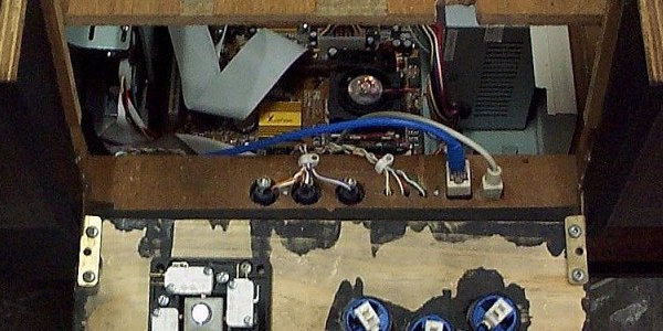
I wired up the controls to a D15 (PC joystick) connector to reduce the chance of breaking the circuit when working in the cabinet. It also makes the wiring in the cabinet a bit nicer.
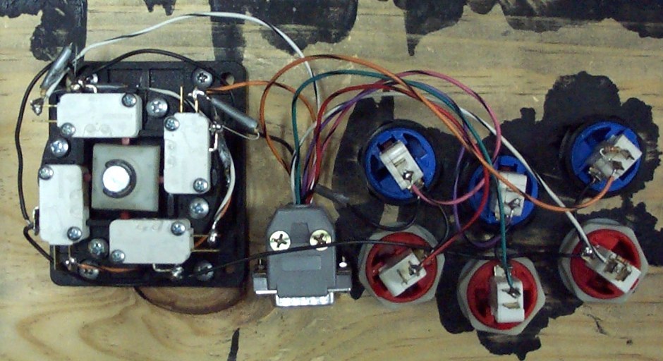
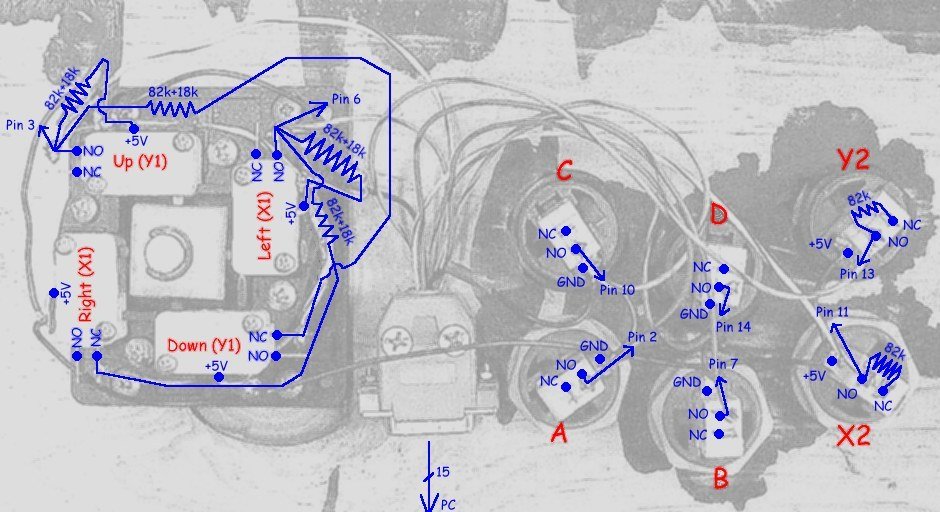
Close-up view of joystick circuit
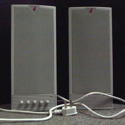
Player 2 and cabinet controls - keyboard hack
The main parts of a PC keyboard are the keyboard controller and the contacts for each key.
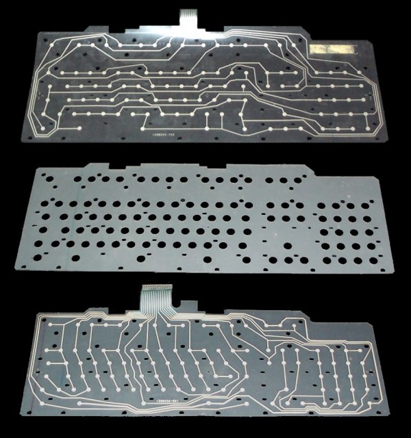
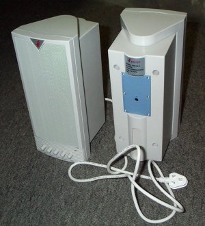
There are 2 sets of wires for the contacts, forming a matrix. The contacts are connected to one wire from each set. When a contact is presesd, the circuit is completed between the two wires. The keyboard I hacked had 16 wires in one set and 8 in the other, giving a maximum of 16x8 = 128 keys.
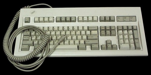
The controller checks for key presses by passing current through each wire in the first set, in turn, and seeing which wires in the second set have current. It then translates the info into something the PC can understand. The limit to the number and combination of keys that can be held down together comes from the controller. The 'keyboard hack' involves removing the controller from the keyboard and wiring up the cabinet controls to your own matrix. The keyboard I used was an old IBM ps/2 model. I had several of them sitting in boxes in the garage, so there were plenty of backups in case I killed one. Inside the keyboard, the matrix was printed on 2 sheets of plastic. The contacts were seperated by a third sheet. The controller was on a small PCB, hidden underneath a sheet of metal supporting the matrix.
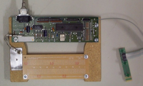
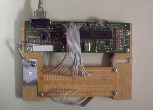
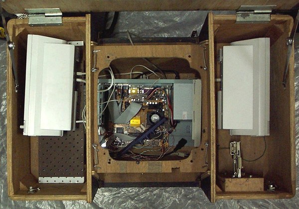
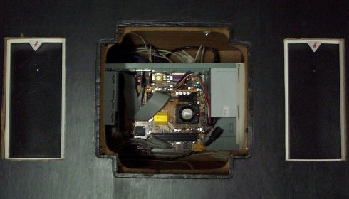
I mounted the controller together with a hobby PCB to make it easier to work with. The first photo below shows the state of the controller before I started working on it. The three black connectors on the top, from left to right are for the 1st set of 16 wires, the 2nd set of 8 wires and the keyboard LEDs. The LEDs are still plugged in at this stage and you can just make out the tracks on the plastic that connect them to the controller. In the second photo, I've removed the connectors and wired the controller to the hobby PCB with some old floppy-drive ribbon cable. It took a while to solder all the wires in place, but it made the rest of the work easier.
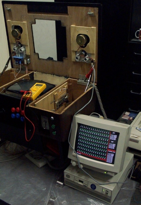
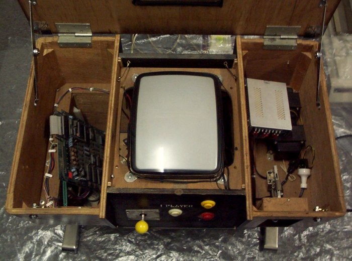
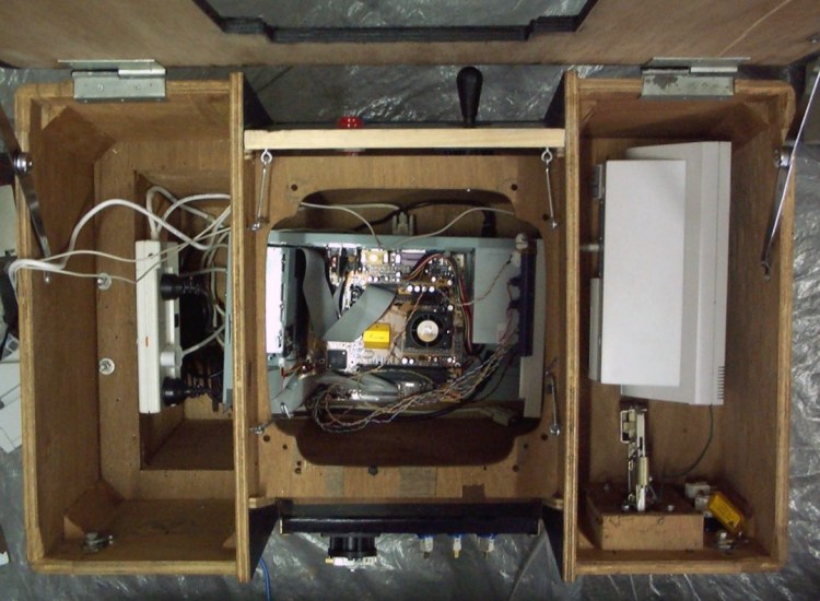
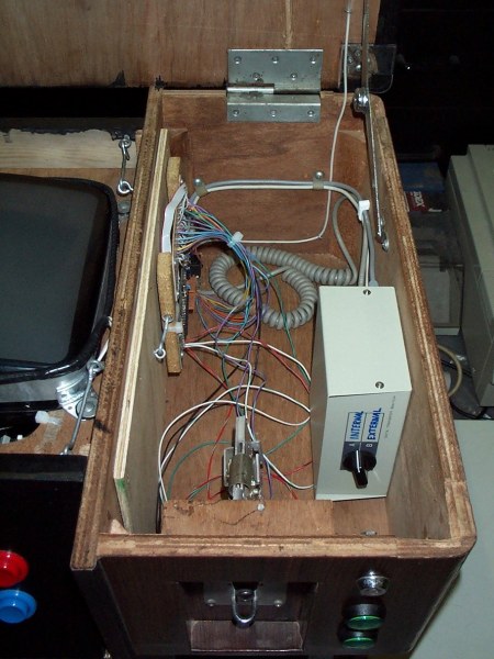
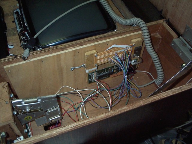
I placed the controller between player 2's controls and the cabinet controls. The mounting is hinged, and swings open, for easy access. The next job was to find out where the necessary keys were on the matrix. To do this, I connected the controller to an old 386 running the same program I used to wire up player 1's controls. The 386 was used instead of the cabinet's PC as it's fairly easy to blow up the controller and/or the keyboard interface on the PC. The matrix I came up with is shown below. It's actually using MAME's standard settings for player 1, as the player 2 standard key assignments have always caused problems when multiple keys are being held down. The 5, 1 & 2 keys are used for the coin-mech, 1up and 2up respectively.
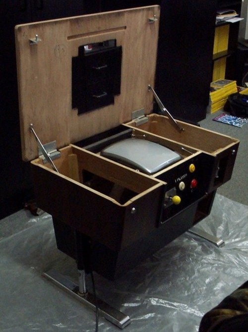
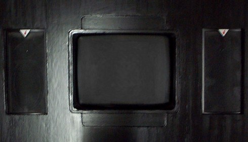
This is the final result. If you look carefully, you can see that the ribbon cable for the set of 16 wires in the matrix is now wired underneatch the PCB. I had to replace the keyboard controller as it broke sometime when I was either fitting or testing it (oops!). The keyboard LEDs for Num-lock and Caps-lock are wired to the 1up and 2up buttons on the front panel. The buttons light up when enough credits are inserted in some games.
