aleax.com

OX CNC Router

This thread details my build of the OpenBuilds OX CNC Machine.

Today I only got about 2 hours into the build (20 mins through the ~2hr long instruction video) before realising that I was missing parts which weren't explicitly listed in the parts list. I'm now waiting for a bunch of bolts to be delivered.

So many parts...

Photo of CNC parts

Heaps of wheels to assemble.

Photo of unassembled CNC wheels

Wheels assembled on one of the z-axis plates.

Photo of assembled CNC z-axis plate

Assembled gantry plates.

Photo of assembled CNC gantry plate

To give an idea of the final assembled size - 1.5m x 1m.

Photo of CNC rails

Test fit of gantry plate.

Photo of gantry plate trial fitment
Last edited by yiannis on 2021-06-20, 05:12:07
yiannis
2014-12-19, 01:00:01

The Bolts arrived, but I didn't get much done. Here are a few more pics.

Making a wheel sandwich

Photo of CNC partial assembly

Top slice.

Photo of CNC partial assembly

Completed assembly.

Photo of CNC completed assembly

Test fit on rail.

Photo of CNC assembly on rail
yiannis
2014-12-23, 01:00:01

The main gantry is assembled. I have to build a table for the router to sit on, as it's now too big to fit on the workbench.

Fitting the lead screw for z-axis.

Photo of CNC assembly

Completed z-axis assembly.

Photo of completed CNC z-axis assembly

The beams weren't quite the same length, and weren't square, so they had to be trimmed slightly. They also needed threads tapped so they could be bolted to the gantry plates.

Photo of trimmed CNC beams

The tabs had to be filed off one side of the corner brackets to give a flush fit against the plates.

Photo of 90-degree corner brackets

Completed gantry.

Photo of CNC gantry.

Mounting the gantry to the rails.

Photo of CNC gantry on rails.
yiannis
2014-12-28, 01:00:01

Here's a pic of the router's new home.

Photo of CNC router installed on table
yiannis
2015-03-01, 01:00:01

Been working on the wiring. Progress is slow and fiddly.

I've decided to use a 350W TFX power-supply as they're smaller than an ATX PSU. The Seasonic SS-350TGM is just the right size to mount on the CNC gantry plate.

Photo of 350W TFX PSU mounted to CNC

I'm using the Spark Concepts CNC controller to drive the CNC. The first enclosure I bought was just a bit too big to mount to the gantry, so I found a nice aluminium enclosure instead. Pity I had to ruin the clean look by drilling/cutting holes where.

Photo of CNC controller assembly

Unfortunately, space is quite limited.. I still need to cut holes in the case for the motors and ATX connector.

Photo of CNC controller assembly
yiannis
2015-03-08, 01:00:01

More wiring fun. I still need to connect the limit switches, but I'm running out of room...

Photo of CNC controller in enclosure

It's alive...

yiannis
2015-04-06, 00:00:01

I've mounted the control box to the gantry and wired it all up. I still need to clean up the wiring a little bit, but at least it's all working.

Photo of mounted control box

There are actually two separate connectors on the PSU side, so I couldn't plug the ATX 24-pin connector straight in from the control box. I tried to create a small adaptor but gave up as it made the wiring look even more messy.

Photo of mounted control box and power-supply

Here's an overview of the entire machine. I still need to put in a spoiler board and level it.

Photo of the entire CNC

I decided to get a proper spindle and VFD rather than a cheapo router, but they haven't arrived yet. To test out & calibrate the router I tried drawing some shapes using a pen. My first attempt used a pen cable-tied to the z-axis, but that didn't work too well as the bed wasn't level. I made up a pen holder using some left over parts - v-slot & 3x L-brackets (one bent at an angle and one cut in two).

Photo of the pen holder assembly

Here's a photo of the assembly attached to the z-axis. The assembly can be adjusted to allow for different length pens, and a spring can be inserted above the pen to allow for some error in the z axis. The pen I was using had a spring mechanism inside, which worked just as well.

Photo of the pen holder attached to the CNC

These are the first two 'prints' to come out of the CNC. The first print, on the left, was printed using the cable-tied pen. You can see where the writing trailed off on the right-hand side due to the bed not being level. The diamond shapes below were supposed to be circles. It turns out the default 'arc tolerance' wasn't set in the controler. Setting this to 0.01mm fixed the problem.

The 2nd print was designed on SketchUp and exported to g-code using SketchUcam. It was printed using the pen holder with a felt-tip pen. The first part of the line was a bit thinner as the pen dried out a bit while I set up the print.

Test prints

The spindle has arrived! Just waiting for the power supply now.

Photo of newly arrived spindle
yiannis
2015-09-19, 00:00:01

Finally had a chance to work on the CNC some more. Had to disassemble the z-axis to replace the v-slot, as it was too narrow to mount the spindle. Also took the opportunity to increase the length of the axis by a few mm.

The spindle is now mounted and wired up. I cleaned up the wiring a little bit, but still not happy with it. Next job is to build the bed, install & level a spoiler-board and build a dust boot.

Photo of CNC with spindle attached
yiannis
2015-09-28, 00:00:01

Had some more time over the long weekend to do some more work. Unfortunately, it looks like the z-axis motor isn't strong enough to lift the spindle. Have ordered a larger one, which will hopefully be beefy enough.

Fitted some adjustable legs on the table to make sure that the corners don't sag, tidied up the wiring some more and test-fitted the bed and spoil board today.

Photo of CNC with spoil board
yiannis
2015-10-10, 01:00:01

Fitted the new z-axis motor and it's solved the issue of not being able to lift the spindle. Also calibrated all the axis.

yiannis
2015-11-17, 01:00:01

Bought a cheap PIPO X8 "TV box" to control the CNC, rather than using the notebook. It should cope well with the dusty environment as it's touchscreen and passively cooled (with vents underneath). It booted up, installed and ran GrblController the first time. I ran through a test file and it completed without any issues. The membrane keyboard in the photo below is terrible to type on, but easy to clean.

Photo of PIPO X8 running GrblController

I tried tested the CNC with the spindle running for the first time and the USB connection kept on dropping out as soon as the spindle was turned on. Damn! I'm pretty sure that it's noise-related, as the drop outs became intermittent with shorter cables. I've ordered some ferrite beads and will see if placing those on the cables makes any difference, especially from the VFD to spindle.

During the trouble-shooting above, I cleaned up the cabling on the gantry some more. It's looking half-decent now.

Photo of CNC gantry wiring
yiannis
2016-01-13, 01:22:06

The ferrite beads helped a bit, but the USB connection was still flaky, so I spent the last couple of days doing what I should have done the first time and re-wired the spindle and motors using shielded cable. I also had to use a larger drag chain, as the new cables were thicker. I fitted an extra set of plugs for the x/z motors rather than soldering the wires together, in case I ever need to replace the cable or motors.

Photo of CNC with new wiring

I decided to mount the PIPO X8 PC on the wall near the VFD. The PIPO has a couple of USB ports spare, so I can plug in a thumb drive containing the files to print. I still need to make up a keyboard shelf, as the touch-screen is a bit fiddy to use to position the CNC before running a job.

Photo of wall-mounted PIPO X8

Finally, here's a photo showing the overall current state. The next step is to build a dust boot and level the spoiler-board.

Photo of CNC room
yiannis
2017-12-30, 23:55:40

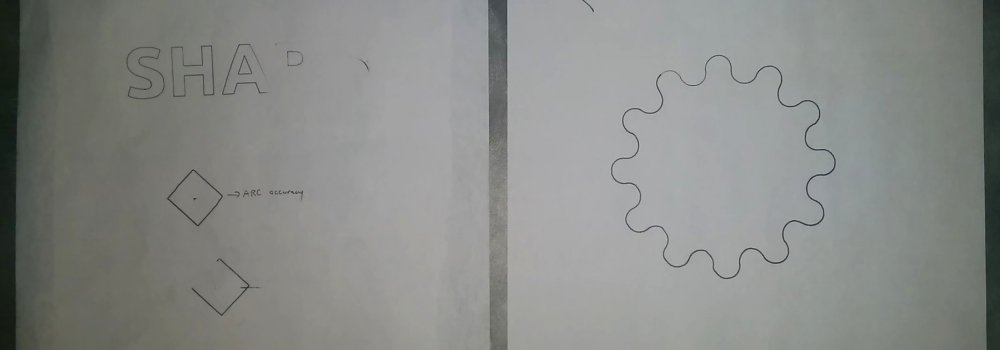
Got a fair bit done over the christmas/new year break - equally spent finishing off the hardware and learning the software.

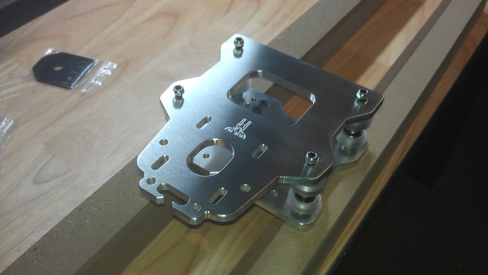
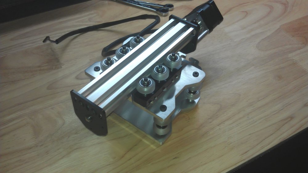
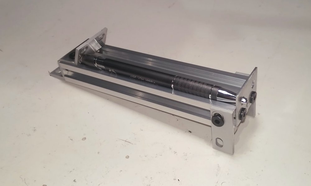
I had a couple of goes at designing and machining some brackets for the torch I'm working on. I used Autodesk Fusion 360 for the CAD/CAM, which is currently free for non-commercial/hobbyist use. It takes a bit of time to learn but seems to be more powerful than I'll ever need.

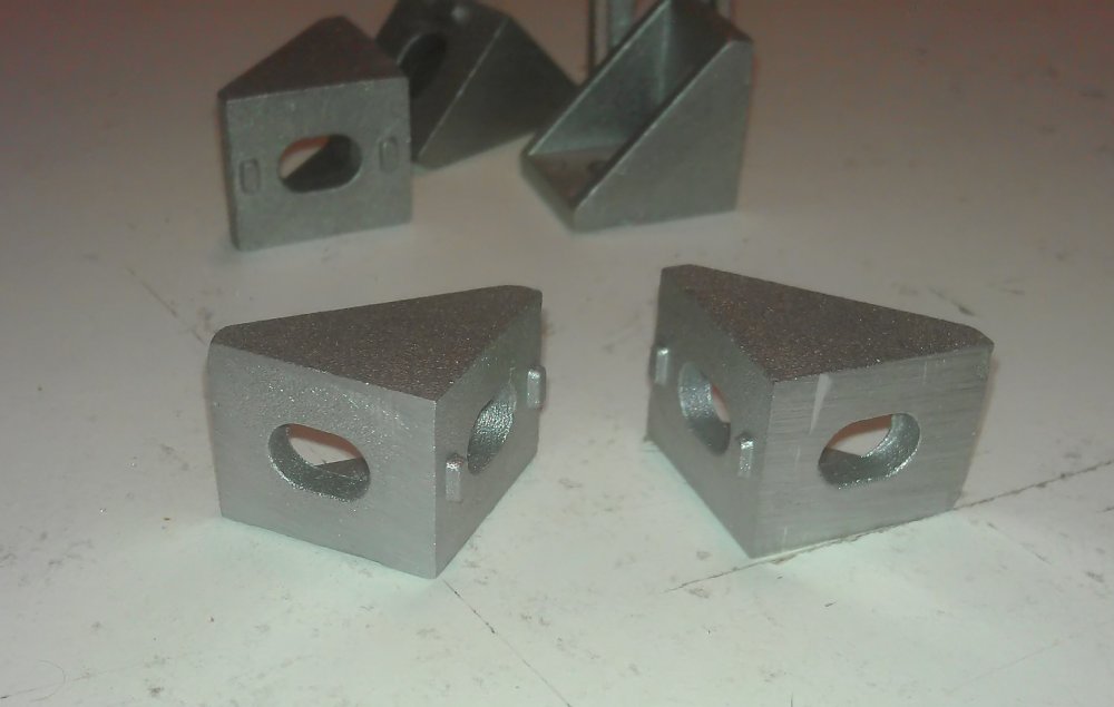
The first attempt failed as I didn't set the stock bounds beyond the bracket model, so the edges got squared off. It was also machined really inefficiently. For example, the entire section in the middle was machined when it didn't need to be.

Photo of carved acrylic

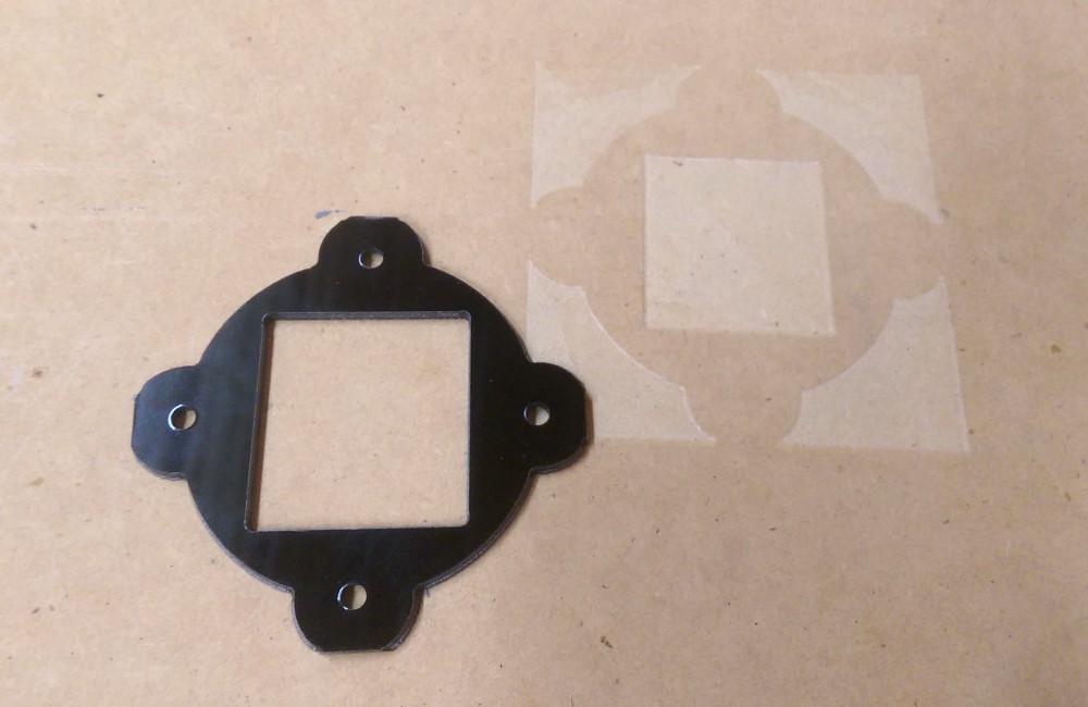
For my second attempt, I added areas to the model to exclude for machining, and added tabs so that the part didn't move. I have since found out that this step isn't necessary - Fusion 360 will do this for you if you select "2D Contour" machining rather than "2D pocket".

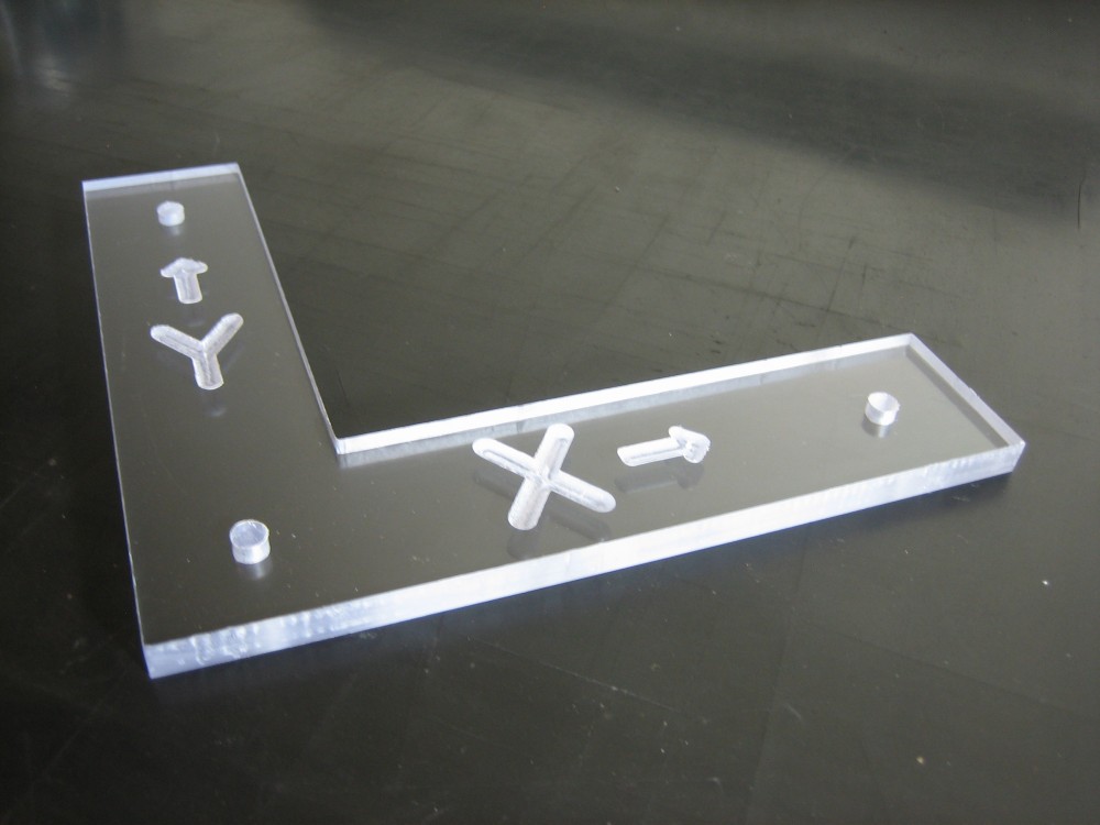
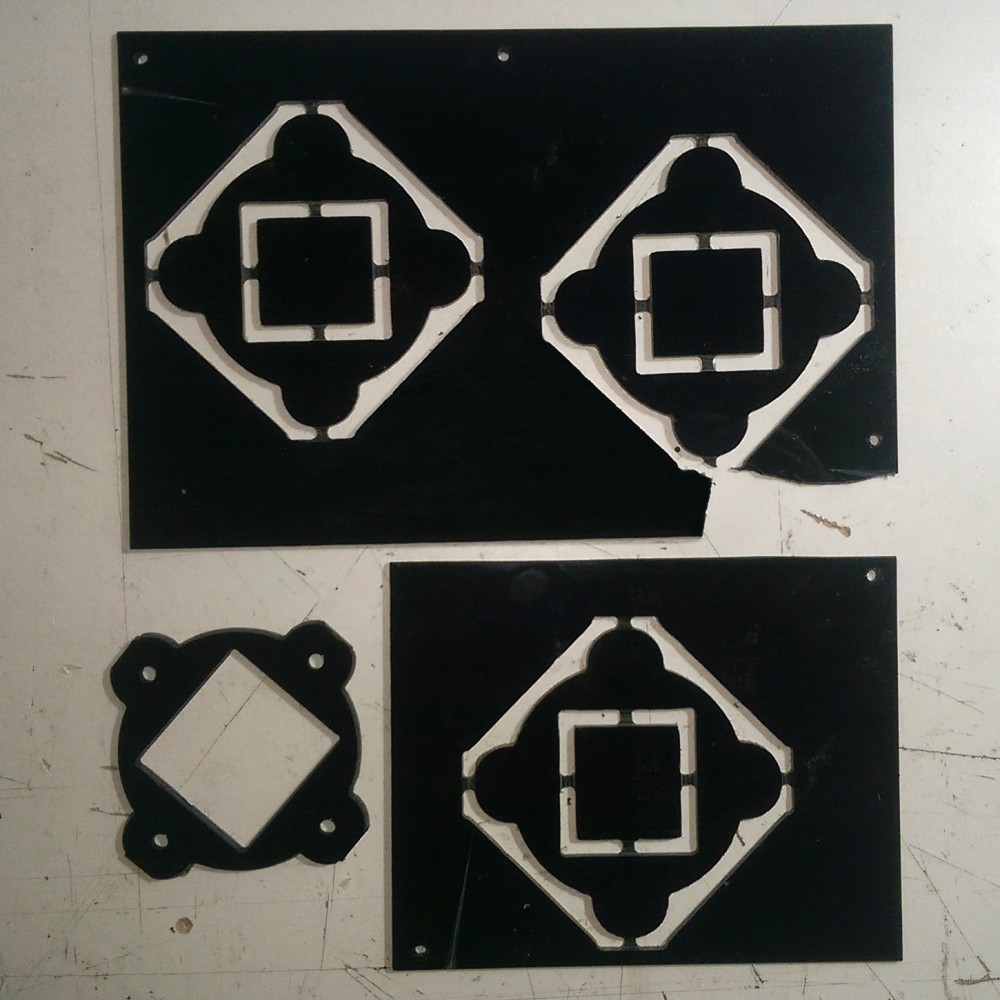
The photo below also shows as issue which occured during machining. At the beginning and end of the program, the machine moved to the origin without retracting the bit to a safe distance. The bottom-right piece has a gouge on its bottom-left where the bit dug into the acrylic at the start of the program. The top piece had the bottom-right corner snapped off when the bit hit the acrylic at the end of the program at high speed. The problem was caused a G28 (go to home) command in the generated g-code. Since I'm using soft limits (no hardware limit switches yet), this command just moves to the point where the machine was powered on. Creating a custom Fusion 360 post-processor with a G1 (move) instead of G28 solved the problem.

Photo of carved acrylic

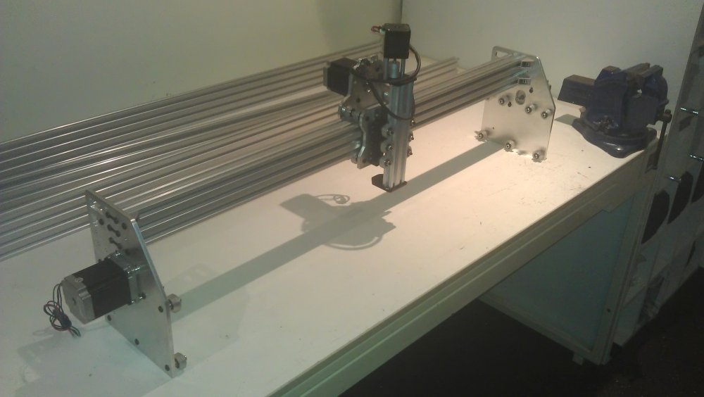
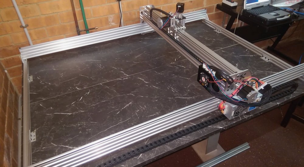
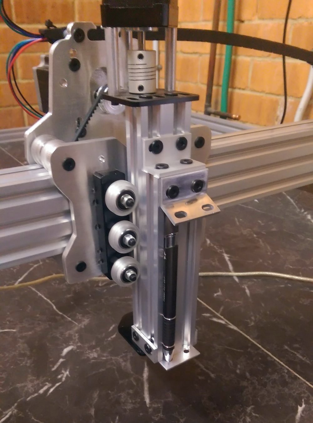
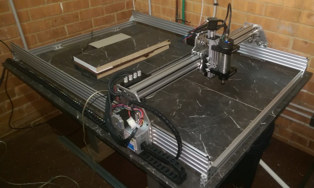
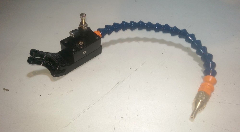
I also installed a compressed air nozzle to flush chips away from the bit. The compressor is a generic 90L/min aquarium pump. I opted for this kind of pump as they're designed to run 24/7, so should easily handle long runs. I installed the pump underneath the CNC table on rubber mounts, to reduce vibration. The air hose runs up the wall to a swinging gantry and then comes down into a flexible arm. The bracket was 3d printed to fit snuggly against the X gantry.

Photo of compressed air nozzle assembly

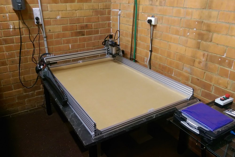
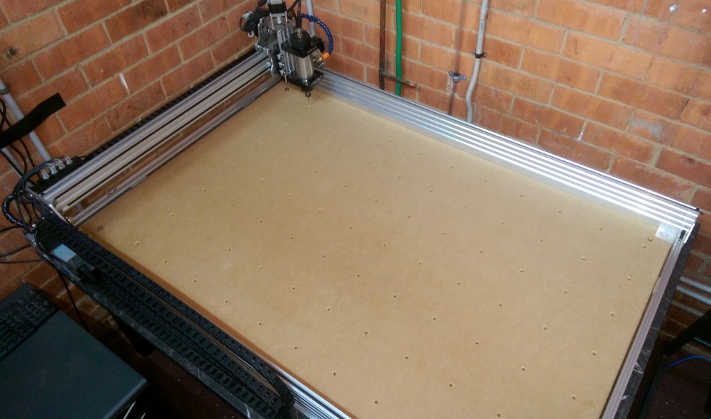
For the test carvings above, I screwed the arylic to a sheet of MDF and then clamped this to the table. This isn't a workable solution long-term, so I needed a better way of fixing the work piece to the bed of the CNC. The two most common methods seem to be T-slot tracks in the bed, or use of threaded inserts. I opted for a grid of 7x11 threaded inserts, as it was cheaper and didn't require me to re-do the CNC bed. Accurately drilling and counter-sinking 77 holes would have been a pain, but luckily I have a CNC to do the boring work. :-)

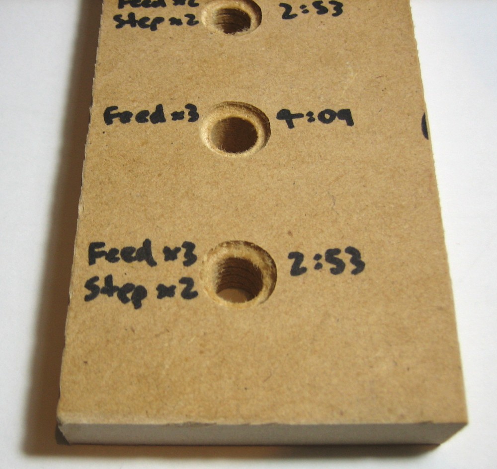
I modelled a tapered hole using measured dimensions from one of the inserts and drilled some test holes with different feed rates / pass depths to see how fast I could go and still have a decent finish. The photos below show the test holes.

Photo of trial runs for insert holes

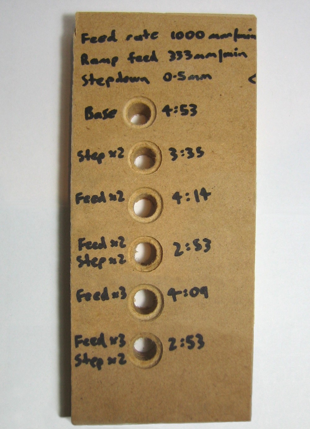
For my reference, the settings used during the test runs were:

Run # Bit Spindle speed (rpm) Cutting feed rate (mm/min) Ramp feed rate (mm/min) Roughing step-down (mm) Finish Elapsed time (mm:ss)
1 3.2mm ball-nose 10000 1000 333 0.5 Good 4:53
2 3.2mm ball-nose 10000 1000 333 1 Poor 3:35
3 3.2mm ball-nose 10000 2000 666 0.5 Good 4:14
4 3.2mm ball-nose 10000 2000 666 1 Poor 2:53
5 3.2mm ball-nose 10000 3000 1000 0.5 Ok 4:09
6 3.2mm ball-nose 10000 3000 1000 1 Poor 2:53

The step-down made more a difference in speed but at the loss of quality. I decided to use the settings from run #4, as increasing the feed rate from 2x to 3x didn't make that much difference in the time.

Close-up photo of trial runs for insert holes

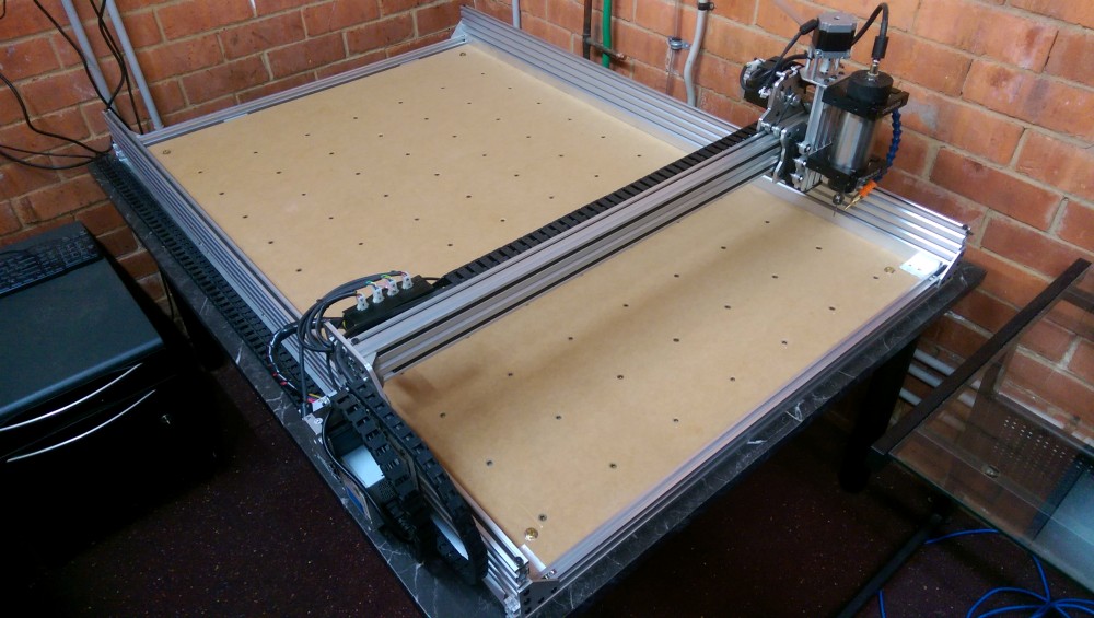
It look most of an afternoon to drill the holes. They were done one column at a time so I could take breaks during the run. Again for my reference, the spacing between the holes is 128.333mm on the x axis (770mm total), and 119mm on the y axis (1190mm total).

Photo of CNC bed with holes for inserts

So many inserts to screw in...

Close-up photo of threaded insert and hole

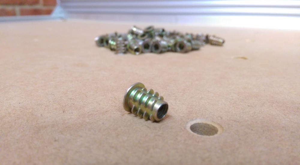
Luckily for me, I had bought a set of ball-end hex drivers for assembling the CNC. I hate to think what it would have been like having to use an allen key. A short while later, and all 77 inserts had been screwed in.

Photo of CNC bed with threaded inserts

Now that I had something to clamp to, I carved some brackets to hold work pieces in place and ordered a set of step block/clamps to clamp the pieces down vertically.

Photo of carved L bracket